|
The Problems
I recently got a rear sway bar from fellow dcfiats.org member Dave Robly to install on my '74 124 Coupe. Thanks Dave! While I had Addco on the phone ordering new hardware
for the rear bar, I also ordered the front bar as well. Figured they were traveling companions, so to say. I loved the
results with the rear bar, so I quickly moved on to the front. BTW - the 1" front and 5/8" rear Addco sway bars
for 124 are the same bars that all of our Fiat parts vendors sell.
I expected the rear bar installation to take some time and exact some aggravation on me - no biggie, done it before. However,
for the front bar I anticipated basically a drop-in job, as it is intended to simply swap out with the stock bar. Not so and
after a three tries, I was unsure whether I want to use it at all. Here’s a quick review of the problems:
1) The Addco supplied center mounting hardware is too shallow and allows the bar to foul on the pinch welded sheet metal
directly above the mounting points. The kit is supplied with washers, presumably to space the bushing mount out, but when
spaced far enough for the bar not to foul on the bodywork, there aren’t enough threads showing on the mounting studs
to get a nut an washer going, nor does the rubber bushing receive any compression from the mating face. I built a 3/16" spacer
plate, but I still had to cut away a little bit of car for the bar to clear.
2) The kit requires that you re-use the existing end bushing bracket from the stock sway bar. Fine idea, but the kit supplied
bushings do not fit into the original brackets - even with "serious persuasion". I spent a little time on the bench grinder
"sizing" the supplied bushing to fit the old bracket with pretty good success.
Okay, got all that? Now finally ready to install - sort of…
3) With the car flat on the floor, the bar is so sprung that it took all I have (at 41, it ain’t as much as it used
to be) to get the bar to fit. I mean I could get the thing in, but its a ball buster. Since the OEM bar goes in and out pretty
easily, I was VERY CONCERNED as to the side load the new bar would put on the lower A-arm bushings.
Pierre Beniston offered me this advice on Mirafiori.com when I posted on the forum looking for what others had done:
"I reused the center mounts by drilling them out to separate them. then reshaped by cutting/pounding the inner bracket
to take the correct sized urethane bushing. Without these center brackets the geometry of the baar is f'ed up. On the ends
I went to a speed shop and bought big one inch bushings and new brakets for them and drilled out and slightly bent them to
fit. My original end brackets worked for a while but eventually cracked. Get bushings designed to be lubed-they have a groove
in the center where the bar rides-fill it wiht grease. I drilled mine out and put a zirk fitting in so I could easily relube
them. "
My Answer
Pierre's solution was a great one, but I was afraid of not being able to undo putting in the 1" bar if I hated what
it did to the handling. So I wanted a solution that would allow me to swap back in the stock bar, but Pierre got
me thinking. I took some basic measurements off the car, cut up the bar stock I'd bought for the spacer plate and did
a little welding.
Here's what I came up with:
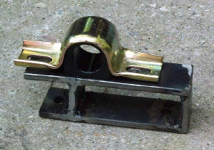
The constructed adapter bracket positions the Addco bar so that its centerline (at the bracket) is the same distance from
the body work as the stock bar. Also it compensates for the bar's incorrect geometry by locating the center bushing brackets
further back. Thus the bar goes in, like the stock bar, without any preload on the bottom A-arm. I suspect I might have to
replace the end brackets as Pierre did, but I'll let it be for now.
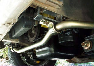
Looks like this installed:
Along with gettin' the derned thing to fit properly, I didn't want to scavenge anything from the old bar, leaving me free
to revert to it if I hated the front bar.
Now the handling is outstanding! I'll post a more detailed drawing of the bracket (with dimensions) when my schedule gets
a little more free.
Construction Drawing:
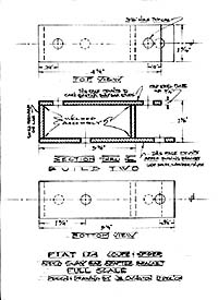
Building The Adapter
If you CLICK on the image left you’ll get a large image of the construction drawing. The adapters I have
on my car I consider the prototypes so what appears on the drawing is how I would build them if I were doing it again.
If you would like a larger file size of the drawing, please feel free to E-MAIL ME and I’ll shoot it too you. The original is drawn at a FAX-able size, so I can also FAX if its needed.
You’ll need 3/16" x 1 - 7/16" mild steel flat stock to start with. I bought mine at The Home Depot,
so a special trip to the steel yard won’t be necessary. For making all the individual pieces, I used a small framing
square and pencil for marking, and cut with a recip saw with a cheap metal cutting blade. I dressed the raw cuts on
the bench grinder to ensure clean assembly.
First, cut all the stock lengths you’ll need. Cut list for two adapters:
2 @ 4 ¾" (top plates)
2 @ 5 ¼" (bottom plates)
4 @ 1 ¼" (spacers)
Before doing any assembly, drill the 3/8" the mounting holes in the top and bottom plates as per the dimensions shown
on the drawing. Once assembled, this is harder to do (ask me how I know). Its a very good idea to use a drill
press for this operation, if available. I also chamfered the holes slightly with the use of a larger drill bit to keep
the metal splinters down when handling the plates, but this isn’t an absolute necessity.
If you haven’t figured out by now, this is a welding project, so at this point you’ll need a welder.
I used my small Lincoln MIG, but I think this could be welded by stick/buzz-box just as easily. Order of assembly isn’t
really that important, but I welded the end spacers to the top plates and the center spacers to the bottom plates first.
I felt this let me get good beads on both sides of each joint before making a final assembly of the two sub-assemblies.
While you have the two subs made up (four really), its not a bad idea to do a dry fitting on your car with the 1" bar
held in place by the end bushing brackets. Note: if you haven’t done the bench grinding of your end bushings,
as previously mentioned ("The Problems" #2), better get to it or the adapter brackets won’t do you much good.
For both the test and final installation, I used metric nuts, lock washers, and bolts of the same size as the existing mount
studs on the car (13mm socket size). The second photo should aid in orientation.
If everything fits up well, then each adapter half can be welded up. If not, then the adapter halves can be adjusted
against each other while in place on the car, marked, then welded to corrected marks. After welding, I dressed the welds
and spatter on the bench grinder. Installation should be straight forward assuming you’ve already done a dry fit
once.
Any questions or problems feel free to E-MAIL ME.
John O.
POST SCRIPT:
As Pierre had warned, my original end brackets eventually cracked. I welded them back up and they haven't re-cracked
yet but then I don't drive the old girl around much anymore.
Updated 4 Feb 2006
|


